 |
Hytec Electronics Ltd. |

|
VME 4-Channel Stepper Motor Controller Type VSMC 2256 Product Description The VSMC2256 is a VME implementation of Hytec’s popular CAMAC SMC1604 Stepper Motor Controller with several very important enhancements:
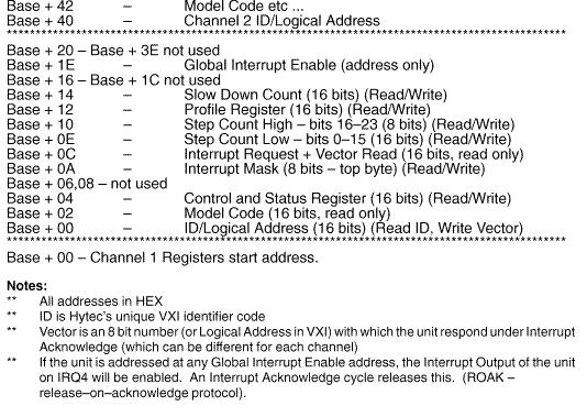
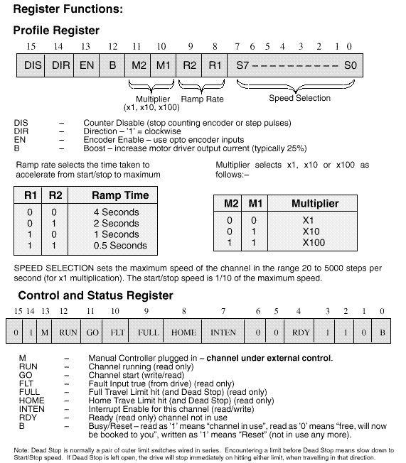
The VSMC 2256 is a single-width dual-height VME slave board. It contains four sets of motor control electronics which work independently to produce opto-isolated STEP, DIRECTION and BOOST outputs for, and respond to LIMIT and FAULT inputs from each of four externally driven motors. Additionally, signals from optical shaft encoders can be input (differential RS 422 with 5V DC supply), which are then counted instead of the step pulses being output. The VSMC 2256 is compatible with Hytec’s rack-mounting Stepper Motor Drive System, the SMDS series. Channel Control Each channel has its own set of separately addressed VME/VXI compatible registers addressed in A16/D16, D08(EO) mode, in line with Hytec’s standard register scheme. Six switches set the Base Address of the module, starting from HEX C000 and incrementing in 256 byte steps. The module occupies 256 bytes of SHORT (A16) addressing space, 64 bytes or 32 words for each of the four channels, assigned as follows:– Interrupts The module uses IRQ4 to signal to the host(s) that one or more of its channels needs service. Provided the channels(s) in question have their Interrupt Enable bit set, then if the Global Interrupt Enable has been given, the unit will assert this line. On receiving an Interrupt Acknowledge Cycle with code 4 on A01-A03, if one or more channels have requested service, then the highest numerical channel will be asked to output its Interrupt Request Register data (16 bits). This outputs the logical ID or vector for the channel (which identifies it) on bits D00 to D07 and also the “reason” bits, bits 8 to 12 from the Interrupt Request Register. Interrupt Acknowledge cycles with different codes on A01-A03 are passed on, as are code 4 acknowledges when no channel has requested service. Operation A motor channel is started (having first loaded Step Count, Profile Register and Slow Down Count) by writing a ’1’ to the “GO” bit in the Control and Status Register. Stepping commences at the Start/Stop speed and increases in frequency at the selected Ramp Rate until Maximum Speed is attained. Each channel has an “ACTIVE” LED which comes on and flashes while the motor is being moved. An internal scanner continuously monitors the number of steps remaining in the channel’s step counter and when the appropriate number remains (determined by the pre-loaded Slow Down Count) a controlled ramp down commences, ending with the motor stopping having completed the desired number of steps. Movements will be curtailed if limit conditions are encountered or if the Fault input (Drive System Fault) is not energised. If the output of an optical encoder is used in the feedback loop then the counter may over-run, which will have to be compensated for by the VME processor. Optional Manual Controller A manual controller is available which plugs in via a 16-way ribbon cable allowing fine positioning of each channel. Each channel counter observes these adjustments. Response Time The unit gives DTACK within 300nSec of the assertion of either Data Strobe. Power Requirements +5V 3 amps, +12V 100mA, -12V 100mA. |


Bits 8, 9, 10 and 12 have corresponding bits in the Interrupt Mask Register, which when written as ’1’ mean “enable this bit as a source of Interrupt for this channel”. Bit 12, RUN, works in the opposite sense, i.e. RUN being false gives rise to Interrupt. The Interrupt Request Register shows 16 bits, which are the logical AND of these Status and Mask bits, along with the loaded 8–bit Vector number.
| Hytec Electronics Ltd Post : 5 Cradock Road, Reading, Berkshire, RG2 0JT, England. Phone : +44 (0)118 9757770 Fax : +44 (0)118 9757566 |