 |
Hytec Electronics Ltd. |
 |
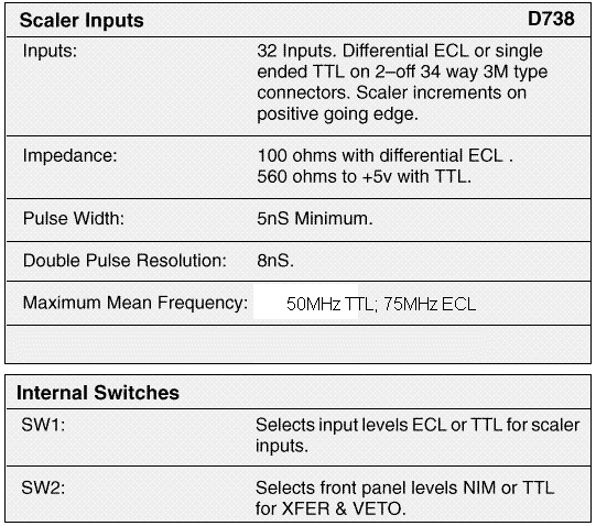
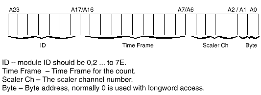
DRAL Multi-Channel Scaler, 24 Bit 100MHz, 32 Channel, 1024 Frame Type EC738 Product Description This dual height VMEbus module provides 32 independent channels of scaling at a 100MHz counting rate, each with a capacity of 24 bits. Each scaler has a 1024 by 24 bit memory into which its contents can be stored under Direct Memory Modify (DMM). This allows the data to be histogrammed into time frames. Inputs can be internally selected to be complementary ECL, or single ended TTL. Pulse widths >5nS are required for a maximum mean frequency of 50MHz TTL, and 75 MHz ECL. Readout of each scaler to the memory is triggered by XFER. This causes the module to inhibit counting for 500nS, while the scaler contents are transferred to the scaler shadow register. It takes an additional 16 uS to transfer the data from the 32 shadow registers to the memory. Readout of the memory may occur at anytime. It is however, given second priority to new data transfers. A test for a status bit will show that the data that has been read is valid. See also the D740 VME Time Frame Generator module (catalogue no. 2383).  VME Interface The module is a slave and interrupter which occupies two areas of the VME memory. The scalers and control registers are in A16(short) address space and allow D32/D16 access. The memory sits in A24 (standard) address space and also allows D32/D16 access. The base addresses for both are derived from the same 8 bit number – the module ID, selected by two hex switches. Registers 256bytes of A16 address space are used to address the scalers, status
register and control bits.  Memory The module requires 128K bytes of A24 (standard) address space to address the memory. The base address of memory is given by Module ID x 10000h (128K boundaries restriction).  Interrupts Interrupts are generated on IRQ1 to IRQ6. There are two interrupt conditions – scaler half full and memory half full. The interrupt status/ID byte is set using the base address switch. Power Requirements +5V at 2.5A. |
| HYTEC Head
Post : 5 Cradock Road, Reading, Berkshire, RG2 0JT, England. Phone : +44 (0)118 9757770 Fax : +44 (0)118 9757566 |