 |
Hytec Electronics Ltd. |
 |
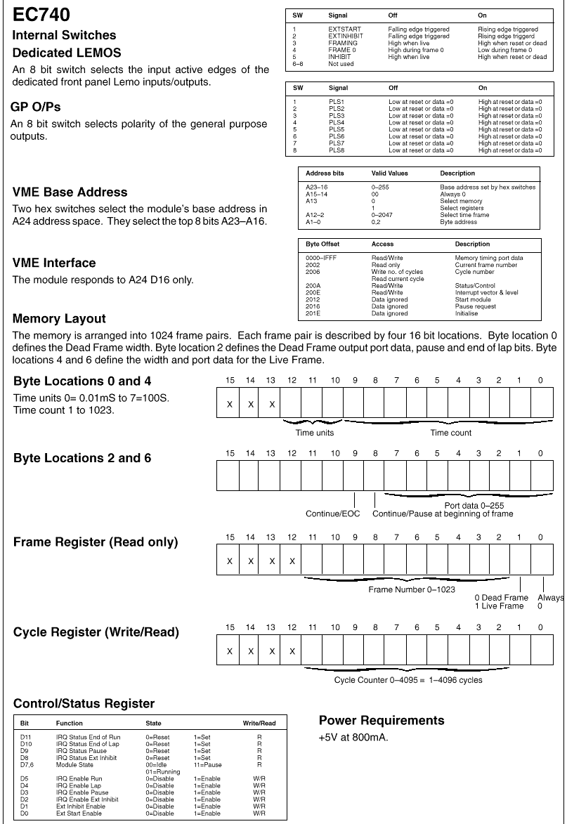
DRAL Time Frame Generator Type EC740 For Use With Scaler Type EC738 Product Description Read this data sheet together with D738 (Catalogue No. 2382) 32 Channel 100MHz Scaler VME Module. The Time Frame Generator D740 is a dual height VME module and is controlled via the use of four registers, they are:–
There are also commands to enable, disable and start the module, and to test and clear interrupts. The TFG module will give from 1 to 1024 time frame pairs. The pairs consist of two time frames, a live frame followed by a dead frame. Each frame in the pair is individually programmable by having 2048 words of memory containing a control word for each frame. The frame at address 0 is always the first live frame, the frame at address 1 is then the first dead frame; the first frame with bit 15 set is the last frame executed before lapping back to the start thus defining the number of frames in a lap. Therefore, the memory address shifted right 1 is the time frame number that external apparatus will see. The lap counter is a 12 bit counter giving 1 to 4096 laps through the time frames. Front Panel Connector Details The front panel provides 2 control inputs, these are the External Inhibit and the External Start Pulse inputs. The inputs are TTL compatible. The External Inhibit input is enabled by setting bit 7 in the status word, when the input is active and bit 7 is set, the unit stops immediately, sets bit 11 in the status word, generates an interrupt and sets the front panel Inhibit and Framing outputs. The module can then be restarted from its current position by a valid start. The active polarity of this input is set by switch 1 in the DIL pack E19. Setting this switch on (up) causes the Inhibit input to be active high. The External Start input is enabled by setting bit 2 in the status word. When this bit is active and the module is enabled, it will start or continue from its position when halted providing that the address and lap registers have not been overwritten. The active polarity of this input is set by switch 2 in the DIL pack E19. Setting this switch on (up) causes the Start input to be active low. The front panel also provides 3 control, 8 timing outputs and the main Time Frame output port which are all TTL compatible. The Control outputs are Inhibit, Frame 0 and Framing. The Inhibit and Framing outputs are the same signal but they have individual polarity controls and can provide complementary outputs. The outputs are active during dead time frames and therefore act as gates to gate the system off at theses times. The Inhibit LED is green and lights during live frames, the Framing LED is red and flashes at the start of each live frame. The polarity of the Inhibit output is set by switch 3 in DIL pack E19. Setting this switch on (up) causes the Inhibit output to be low during dead time frames. The polarity of the Framing output is set by switch 5. Setting the switch on (up) causes the Framing output to be active low during dead time frames. |

| HYTEC Head
Post : 5 Cradock Road, Reading, Berkshire, RG2 0JT, England. Phone : +44 (0)118 9757770 Fax : +44 (0)118 9757566 |