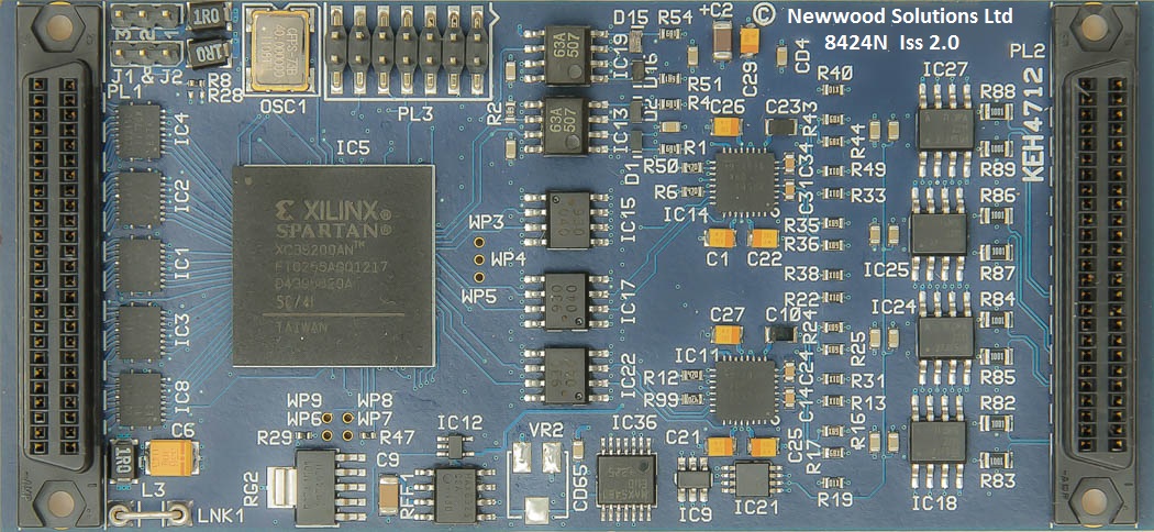
ADC8424
4-Channel 16-Bit ADC 1MSPS
WITH TRANSIENT RECORDER FUNCTION
IndustryPack®
The Newwood Solutions Ltd IP-ADC-8424 is an Industry Pack® that provides 4 channels of simultaneously sampled analogue digitisation with the following characteristics:-
• Up to 1MHz sampling rate on 4 independent channels (one ADC per input).
• True full differential inputs.
• Input impedance - 10Mohms differential.
• Resolution - 16 bits no missing codes.
• Accuracy - 14 bits.
• On board RAM Memory 1M x 16 bits (256K conversions per channel).
• Programmable full-scale resolution all inputs +/-10V or +/-5V.
• On-board calibration by FPGA firmware using stored offset and gain.
• Gain drift - 4ppm per deg C (typ).
• Offset drift - +/-10uV/degC (typ).
• +/-10V offset error - +/-2LSBs with firmware calibration (+/- 2mV without calibration).
• +/-5V offset error - +/-4LSBs with firmware calibration (+/- 2mV without calibration).
• +/-10V gain error - +/-2LSBs with firmware calibration (+/- 5mV without calibration).
• +/-5V gain error - +/-4LSBs with firmware calibration (+/- 4mV without calibration).
• ADC voltage reference drift - 2.0ppm/oC (max).
• CMRR: - 100dB at +/-5V wrt plant CMV (92db typical at 100KHz).
• Aperture Delay - 15 ns typ.
• Aperture Delay Matching - 70 ps typ.
• Aperture Jitter - 50 ps typ.
• Over voltage - +/-25V on or off.
• On-board sample clock programmable (1MHz, 500KHz, 200KHz, 100KHz, 50KHz, 20KHz,10KHz, 5KHz, 2KHz, 1KHz, 500Hz, 200Hz,100Hz, 50Hz, 20Hz,10Hz,
5Hz, 2Hz and 1Hz).
• Ext sample clock isolated input.
• Ext trigger/start isolated input.
• Ext Stop isolated input.
• Ext sample clock isolated output.
• Ext trigger/start isolated output.
• Ext Stop isolated out.
• System to plant isolation to 100V when externally powered by DC/DC converter option.
• Board type, Serial number, PCB issue and firmware issue held in ID PROM.
• 8/32MHz IP system clock operation.
• Field upgradeable firmware from IP bus or from JTAG port.
• EPICS and ASYN driver support.
Size: Single width Industry Pack 1.8ins x 3.9 ins
Operating temp: 0 to 45 deg C ambient
Number of channels: 4
ADC resolution: 16 bits
Diff. Non-linearity: +/-0.75 LSB TYP
Int. Non-linearity: +/-1.5 LSB TYP
+/-10V offset error +/-2LSBs with firmware calibration at a sample rate of1MHz at 25 deg C (+/- 2.5mV without calibration).
+/-5V offset error +/-4LSBs with firmware calibration at a sample rate of1MHz at 25 deg C (+/- 2.5mV without calibration).
+/-10V gain error +/-2LSBs with firmware calibration at a sample rate of1MHz at 25 deg C (+/- 5mV without calibration).
+/-5V gain error +/-4LSBs with firmware calibration at a sample rate of1MHz at 25 deg C (+/- 4mV without calibration).
Offset drift: +/-10uV/degC (typ).
Gain drift: 4ppm per deg C (typ).
Range: +/-10V or +/-5V full scale (+ve input referred to –ve input)
Overvoltage: +/-25V
Bandwidth (-3dB): 750KHz
Throughput: 1MHz
SNR: ADC Signal-to-Noise 90dB(min) 93dB (typ)
SINAD: ADC Signal-to-Noise + Distortion (SINAD) 89dB(min) 92dB (typ)
Isolation: 100V via opto-isolators (if externally powered)
ADC device: TI ADS8363
Data format: 16 bits straight binary
Memory: 1M x 16 bits (4 channels gives 256K conversions per channel).
Power:
+5V @ 200mA typical
+12V @ 130mA typical when switched to internal
-12V @ 60mA typical when switched to internal
The ADC8424 had a Transient Recorder mode. In this mode an external/software trigger stars the digitisation after a
user programmable time delay. Digitisation continues until stopped by external stop signal, software stop command,
memory overflow or after a set number of conversions as set by the user.
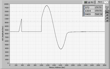
During this time the unit monitors the upper and lower thresholds set by the user. If the thresholds are reached the
unit logs the address of the sample memory where it occurred. It also logs the peak value for all channels.
In Transient Recorder mode the unit also has a voltage trigger function. This function allows a pre voltage trigger
buffer to be set up in the memory. Here the external/software trigger signal starts digitised in to a circulating buffer
until the signal reaches the lower threshold value. The memory pointer is then set to the start of the post trigger
memory buffer and logging carries on until the end of the memory is reached or the set number of sample has been
logged.
Downloads